It is time for another update about my hobby project. I have been working on a module to perform basic operations on the geometry used to perform CFD simulations. Originally my application did this inside the module used to configure meshing with snappyHexMesh. However, this directly linked the geometry assembly to the mesh. I wanted to separate the two tasks for two reasons:
- Allow the same geometry assembly to be reused in multiple simulations. This also allows to reduce the number of times the same geometry information is stored, which is good side effect.
- Reduce the complexity of the mesh configuration tool.
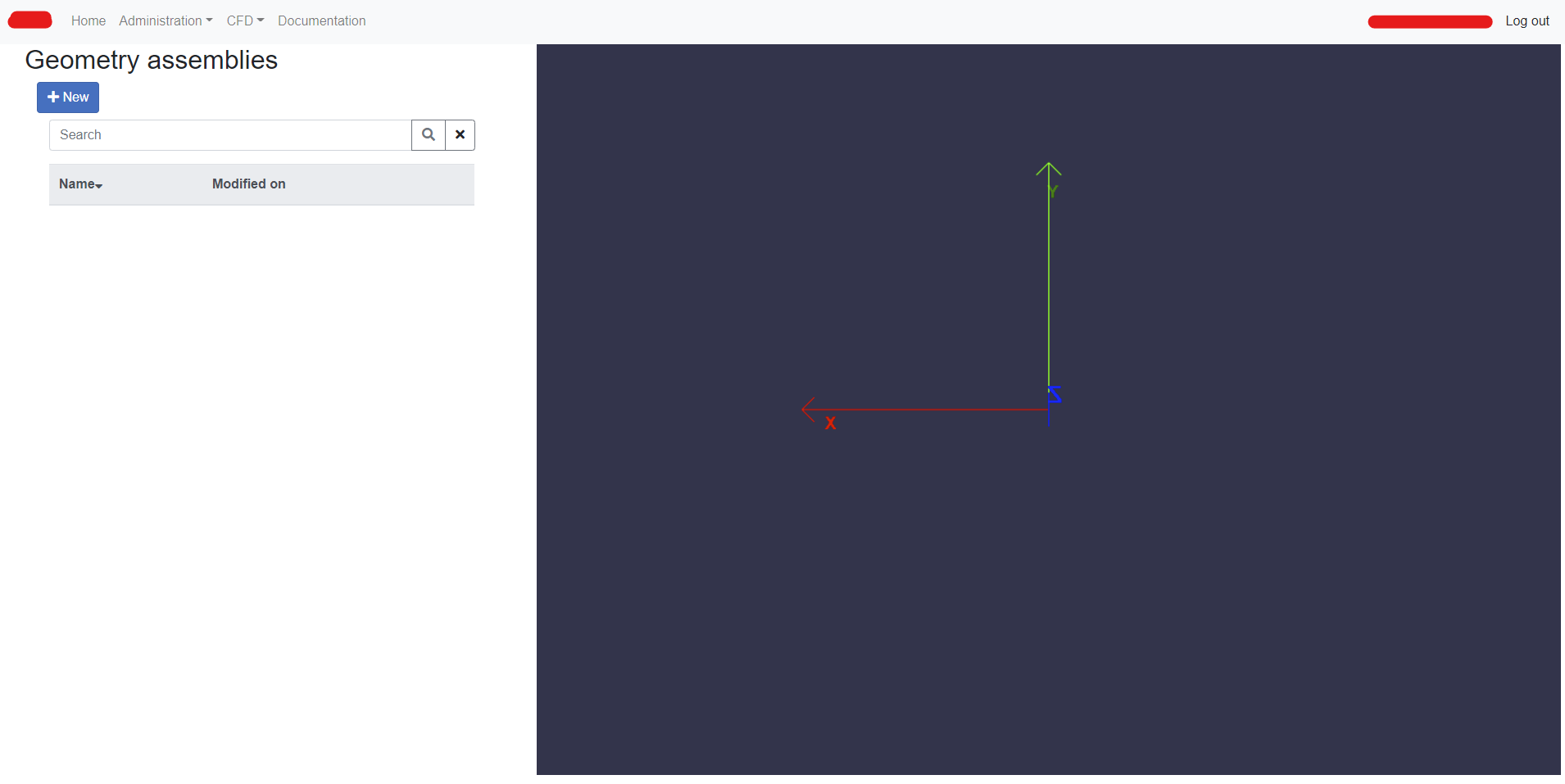
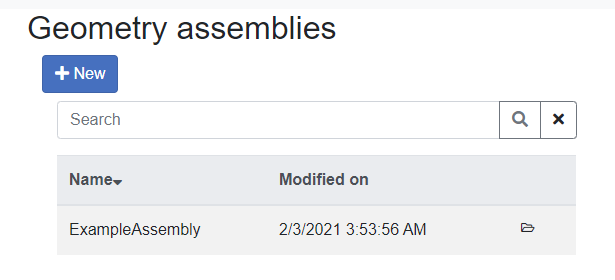
Focus of this update is the part of the app that allows the creation of geometry assemblies from both simple analytical shapes and STL geometries. The landing page looks like the following:
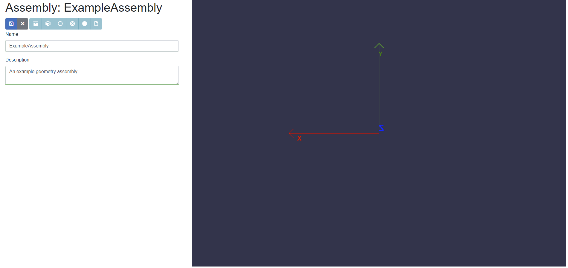
After clicking on + New, the basic information of the assembly is requested. Only Save and Cancel are allowed actions at this stage.
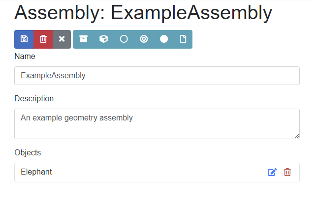
After pressing Save, the interface is updated and the other options become available:
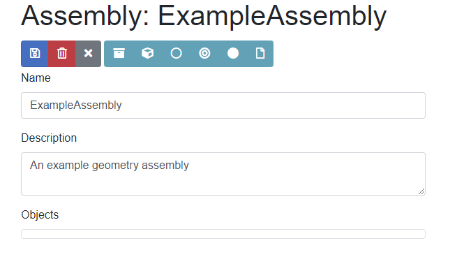
In the order, the buttons with secondary color are:
- Geometry file library
- Box
- Cylinder
- Hollow cylinder
- Sphere
- File upload
The latter only allows to upload geometry files (STL and OBJ) to the Geometry file library, which is an archive that allows files to be reused in multiple assemblies. Files belong to the user who uploaded them and only such user can use them. At the moment, a maximum file size of 100 MB is allowed, due to how files are stored and managed. User’s geometry files can be seen in the Geometry file library:
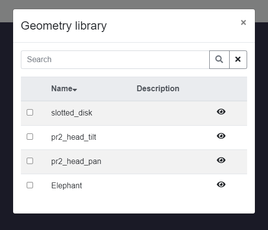
The library is searchable by name and description. If either contain the string inserted in the search box, files will be show in the list. The checkbox on the left of the file name allows the file to be added to or removed from the assembly. The eye icon expands the Geometry library modal and shows a preview in a GL canvas: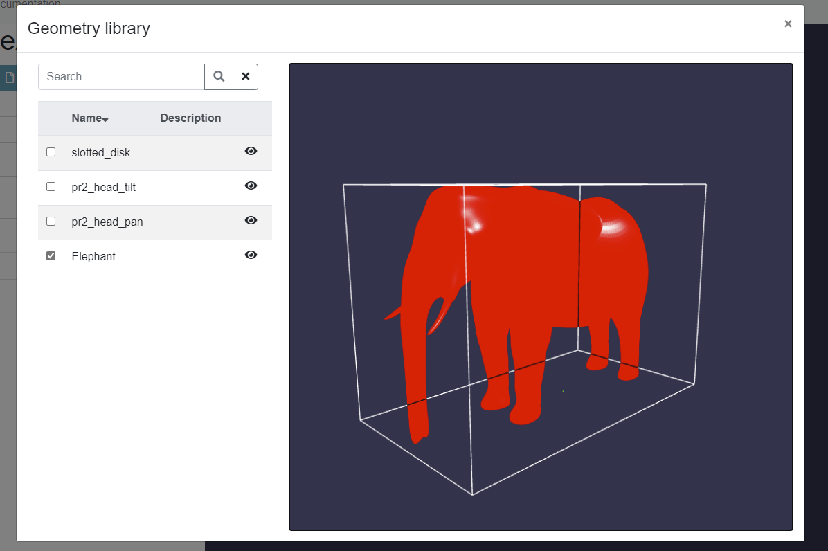
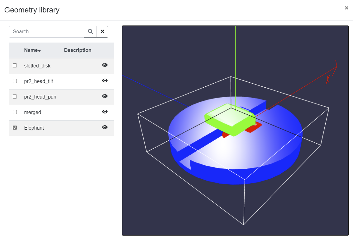
The object is automatically zoomed in to fit into the size of the modal and the bounding box is determined and visualized. The GL canvas is active and allows the object to be zoomed in and out and rotated with mouse or touch controls. If a geometry file has multiple solids, each is assigned a different color automatically:
The list of object has three main features:
- Clicking on the object name highlights it in the GL canvas making it semi-transparent.
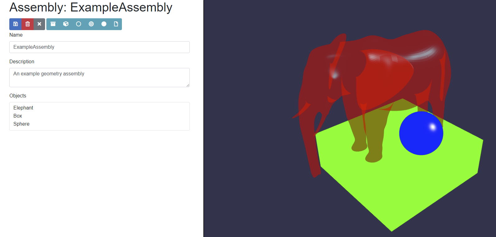
- Hovering on the name shows the Edit and Delete icons.
If the object is a file, the following modal dialog is opened when clicking on the Edit button:
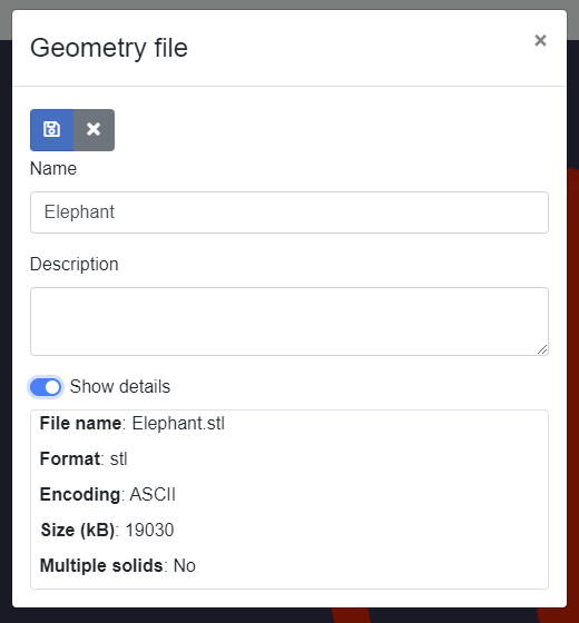
Details of the geometry file are shown. If the file has multiple solids, their names are shown too.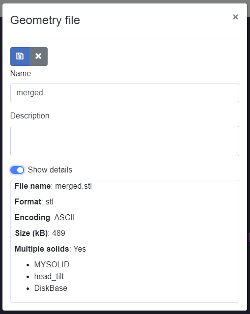
Similarly, for analytical shapes, dialogs with the information needed to define the geometry is shown. For example, for a box: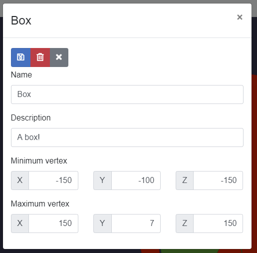
and for a sphere: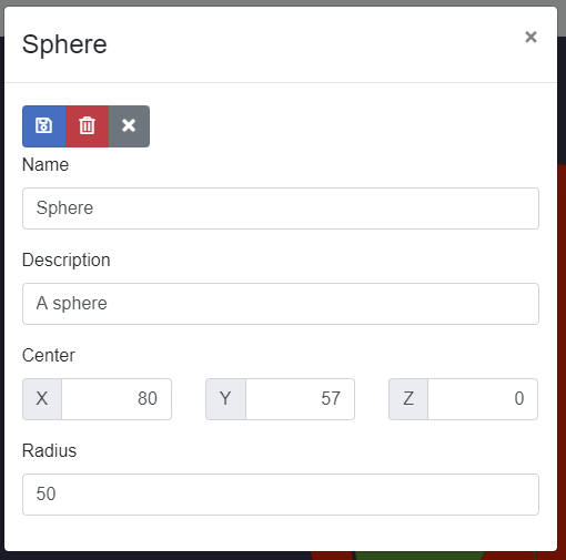
Finally, geometry assemblies are listed in the main page, and can be opened by clicking on the folder icon:
 This is all for this update. The next step, after cleaning some code up, is to integrate the geometry module with the mesh configuration part of the app.
Enjoy 😀
This offering is not approved or endorsed by OpenCFD Limited, the producer of the OpenFOAM software and owner of the OPENFOAM® and OpenCFD® trade marks. Alberto Passalacqua is not associated to OpenCFD Ltd.